AWA Broadcast
Equipment
It's aim to preserve Australian equipment and images before it is all gone.
AWA was a Giant in Australia and New Zealand, they made virtually every type of electronic thing.
- AWA set up coastal radio stations before WW1,
- Received the first radio signal in Australia from England in 1918.
- Built and ran the first LF and MF broadcast stations in 1923 and 1924.
- "Radiotron" valve manufacture commenced in May 1933.
- Designed and built radio location equipment (RADAR) used by Australian and USA forces in WW2.
- Manufactured defence equipment such as shell fuses and aircraft equipment.
- Built radio and TV receivers, traffic light controllers, telephones and telephony equipment.
- Designed and built TV transmitter equipment based on improved versions of Marconi & RCA.
- Designed and manufactured transistors and intergrated circuits.
- Built the tallest building of the era in Australia; 47 York St, Sydney.
The manufacture of broadcast equipment (and receivers) in Australia virtually ceased because of:
- Union driven rapid increases in pay rates.
- Whitlam government introduced a 25 % import tariff cut on July 18, 1973, intended to cut inflation.
- In the end AWA was sent broke by a rogue currency trader.
New transmitters use much less electricity and save enough on electricity bills to pay for themselves.
Newer broadcast technicians are sometimes not comfortable with valve technology.
People who operate the older transmitters usually as a stand-by, say that they are more reliable in thunder storm weather than the modern replacements.
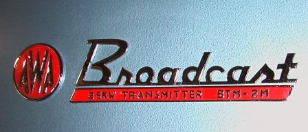
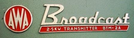
AWA logo and Broadcast logos (above) of the 2 transmitters directly below.
AWA was the first company to manufacture broadcasting equipment in Australia
around 1923-4 and continued production for half a century.
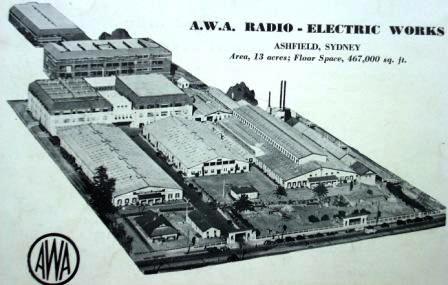
AWA factory Ashfield, Sydney about 1946.
AWA Broadcast
Equipment
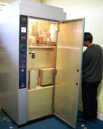
AWA 2 kW
from about 55 years ago.
Photos of two related AWA 2,000 Watt AM Broadcast Transmitters from about 55 years ago.
installed originaly at Sale Vic. 1966; and later at Warrnambool.
It ran on 3 phase 415 V power and drew 20 Amps per phase The Warnambool site was demolished in 2007 being returned to pasture. Unfortunately only single phase power is available at its new home. The control circuit, minor HT, air blower and The 5,500 V a.c. output three phase transformer It can be run again as before but only up to
It's a thrill to push the "Filaments" button and |
 |
This is similar to unit above.
I have included this unit with the BTM-2M
Apart from being mostly transistorised less paint, Transmitters would be bought on: price,Aesthetics would not matter greatly. |
 |
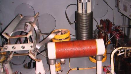
Modulator valves on the left, push pull 4/1000A and 5762 output valve on the right. The coil is for neutralising. The main H.T Voltage was 5,000 V d.c. |
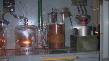 |
The valves on the right are the RF drivers QE05/200. These valves are unusual, they have 3 indirectly heated cathodes. Earlier versions had only a single QE05/200. Below these valves are the 6AK5 oscillator and 5763 tuned amplifier.
The audio input was 2 by 6BK8 equivalent to, and now replaced by 2 by EF86,
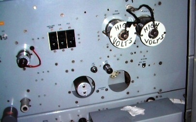
The 3 (black) circuit breakers are for; |
 |
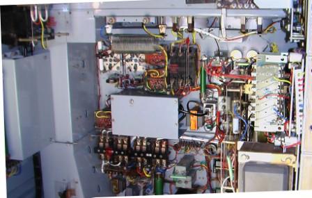
| BTM-2A Solid State version except for the two modulator output and modulated amplifier valves.
This photo is of a BTM-2A used at a commercial station
The box on the lower right holds the
The aluminium inside of this transmitter is not painted.
Blythe of New Zealand, have supplied many |
 |
the coil on the left is the tuning coil The more distant coil is for matching the orange coil is a R.F.Choke.
There is also an SWR transducer and a |
 |
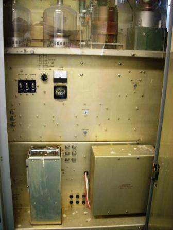
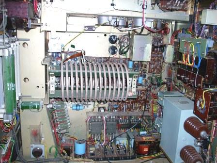
modulator and RF low power stages. The minor HT supply is on the right. On the left there is the fored air duct to the power valves above. The holes in the duct cool the low power stages. |
 |
Mid-rear view showing main 415V 50 Hz 3 phase contactors modulator and RF low power stages. The minor power supplies are on the right. On the left there is the fored air duct to the power valves above. The visible holes in the duct blow air to cool the large resistors on the left.
The large grey capacitor on the lower right |
 |
Many of the original fastners had been lost during 40 years.
Restoration included sourcing replacement ¼ turn "Oddie" fastners.
Quickly removed and installed fasteners are a safety feature. |
 |
 |
|
from the old valve AWA signal generator, through the BIG-1 Limiting Amplifier all formerly from Warrnambool, as shown lower down this web page.
The audio negative feedback is not operable in this photo |
 |
AWA 500 Watt Broadcast Transmitter
from 60 years ago
and still used as a stand-by.

 | This example formerly was 3KZ's stand-by transmitter
I found the unit pictured left, one lunchtime after
I quickly found the transmitter, just 700 metres away from my employers' office.
Two of these could not be given away in Adelaide. They were taken to the tip. |
AC power usage is 2600 watts at 100% modulation. The meters are: RF output amps, HT voltage (about 3 kV) and PA anode current.
The thermionic valves used show a family resemblence The oscillator valve is 6AK5, |  |
The sides are each quickly removed by 4 Oddie ¼ turn fastners. The heavy components such as transformers and blower are mounted in the lower section. There is an air filter on the lower left side. Air is exhausted out the top. Other AWA BTM-P5 Survivors; |  |
 | 
4AY Innesfail Serial Number 1 |
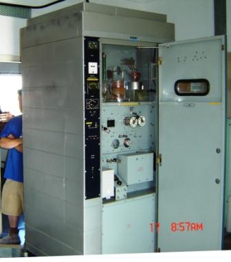
AWA 5000 Watt Broadcast Transmitter
from 40? years ago
and still standing-by |

3CV at near Maryborough, central Victoria. AWA 5kW on 1071 kHz now used as Stand-by. |
 |

Above; right hand side Radio Frequency Amplifier controls.
|
AWA 10 kW
from 50 years ago
I took this photo in 1987. I went past the station in 2004, the original large, white, weather board transmitter building had been replaced by a transportable hut. No doubt the transmitters pictured had gone too.
The modulated amplifier had 3 valves in parallel (5762, I believe). Coming from the phone buisness he wouldn't have been taught
The stand-by transmitter was an AWA 2 kW the same, |
 |
 | This model of transmitter is similar to an RCA 10 kW of the same era. |
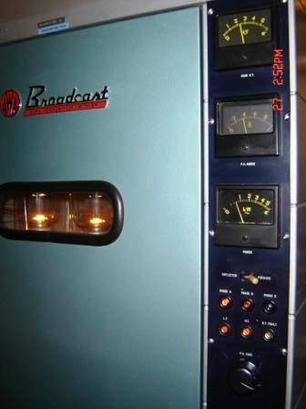
AWA 2 kW
from 60 years ago

I like the art deco style. The sparrows don't appeciate it. The meters at the top were to monitor the routine functioning of the transmitter.
Behind the smaller central door are meters and controls Normal versions were suitable for 50-60 Hz.
AWA made special transmitters suitable for 40 Hz mains operation Some versions had an Aerial Ammeter for remote monitoring of the actual aerial current when connected to an AWA antenna tuning box. |  |
 | |
 |  |
 |
Above left; power supplies and power control relays
Above right; Radio Frequency panel on left and output coupling panel at rear. Left; the power supplies and power control are at the rear All components that could contain
A similar model transmitter may be |
 | AWA Crystal Oven with original factory lead seal on the side imprinted with "AWA" |
from the same station marked with 1130 but remarked 1134. The crystal in the centre is surrounded by a heater element that is wound on a copper former with a thermostat switch.
This style of crystal oven was produced over many years. Australian broadcast stations changed frequency from 10 kHz to 9 kHz channel spacing in 1980. The crystal oven is contemporary with the transmitter
It plugs in to the oscillator unit shown in the bottom left It would be usable in all of the AWA transmitters above. |  |
in approx 1948 on stand-by at 2CO Corowa, in 1987. The power valves were AWV Radiotron 833.
This style of transmitter was available in various outputs; The rectifiers were mercury vapour 866 and 872. AWA transmitters had internal lighting. The same transmitter is in the tow photos below. |
 |

The same transmitter in about 1949 with operator Mr Colin King.
|

Same former stand-by 2CO transmitter. |
 | AWA 500 Watt MF from about 1950
This model used 3 by 810 valves in the modulated amplifier. The web master hopes to obtain a photo of a surviving unit in the future.Photo from Radio 1 (1952 reissue), PMG Engineering Department, Tresuary Gardens, Melbourne.
|
AWA 10 kW Television Broadcast
2 kW Aural Transmitter
from 45 years ago
 | Left: Logo on the front of the sound part of the transmitter.
AWA imported English Marconi TV transmitters into Australia from about 1956.
The Australian 625 line system had about 5 MHz video bandwidth; AWA adapted an RCA design to Australian conditions and commenced manufacture of TV transmitters in the early 1960s. |

This TV transmitter (Aural section) shown above in use for FM sound Broadcasting. The vision transmitter having been retired some time ago. The vision transmitter part extended about 4 feet further to the right of the third cabinet section. Total width 9 feet 10 ½ inches, depth approx 19 inches, height 7 feet. | AWA 2000 Watt FM Transmitter from about 1964.
and still soldiering-on strongly on ANZAC Day 2009.
Another idenical unit for another station is also in service to the right foreground where just the edge of the cabinet can be seen.
Photo above is of the combined control panel of the vision & aural transmitters.
The complete TV transmitter, sitting disused and dust-covered in a shed for years, The 4 kV H.T and 7 kV E.H.T. power transformers, rectifiers and blowers were housed seperately from the transmitter. It was eventually turned off for last time at 09:24, Monday, 7 September, 2009. |

.
Contact me
d.j.bainbridge(substitute at symbol)bigpond.com
Links
- Video of AWA & STC transmitters
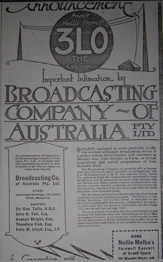
- Await Hello from 3LO
(AWA built and installed and operated the 3LO Transmitter based on Marconi technology no doubt)(Large 1 Meg. file) - Link to Kurrajong Radio Museum